Monday 16 August 2021

8 Tracker Revisited

During the Covid outbreak I had plenty of time to think about how the basic Mark 3 module design should be deployed in a real mixer. All the basic technical issues like mechanical rigidity, screening, attachment of front panel controls and finding the right low profile audio transformers have already been addressed but exactly what features and functions need to be included in a channel amp? The Channel One design fulfils all the basic needs of a stand alone mic/line pre and 3 band EQ but it includes nothing to help it function in a full mixer intended for both tracking, overdubbing and mix down. All that kind of thing is assumed to be external. The Channel One also had a lot of internal wring, much of it carrying low level signals so I wanted to look at how this could be reduced.

So, with the benefit of time on my hands I decided to step back to the old 8 Tracker design and began to think about how you would actually use it. For tracking the Channel One was fine. Mic and line inputs, stepped mic gain and a 3 band REDD EQ and a pre fader direct out. But 3 band EQ is a bit low end these days and there is a kind of natural 4th EQ band between the low and mid bands of the REDD EQ so I decided to look at squeezing in another EQ band.

So what about overdubs? You could feed the tape returns into the line inputs and manually switch each already recorded track from mic to line before you overdub but that is a bit cumbersome especially if you already have the line inputs wired up for synths for example. You don't really want to have to go round the back of the console and re-plug it every time you overdub. What you really need is a separate tape return input to the channel amp so you can just flip already recorded channels to tape play for overdubs. This could go through a big pad and into the mic pre just like the line ins but then you would end up tweaking the mic gain switch to set the tap return level. The tape return clearly needs its own trim control so it might as well bypass the the mic pre all together. So we need to find room for a tape return pot and switch.

Lastly, for mix down, we need to switch every channel input to its tape return. Again it would be tedious to have to flip every tape return switch on every channel to ON. So if the tape return switch operated a relay that switched in the tape return, we could have a big REMIX button in the monitor section that turned on this relay in every channel so they all flipped to playing tape returns in one go. However, even in REMIX, you might want to use spare channels for AUX returns so you need some way to override the auto REMIX action. And you still need to be able to flip individual channels to tape during overdub. In the end I came up with a three position switch that sets the "MODE" for each channel. The normal centre position is AUTO. Mic and line inputs work as normal but the monitor section REMIX button switches the channel to tape return. If you want to use the channel as a mic/line pre instead, you flip this switch to the REC (record) position which permanently overrides the tape return. For overdubbing, if you want to switch an individual channel to tape return the you flip this switch to PLAY which sets the channel permanently into tape return mode.

So we have added a relay for the tape return switching which leads naturally onto thinking about what other signals could sensibly be switched by relays so as to save on wiring. The mic and line inputs seem good candidates. Both have to be routed from the 32 way connector at the rear of the module, past three hot tubes to the front panel and then back to the mic input transformer. If they could both be routed to some relays and then into the mic input transformer the route would be much more direct and we would save three bulky screened leads. I came up with a design that uses four miniature DIL relays. One for the 48V phantom supply, one for the mic 20dB pad, one for the mic line selection and lastly one for phase inversion. Their dc control voltages connect to the front panel via a single 6 way ribbon cable. An added advantage of this method is that we can combine two functions into a single switch and thereby reduce the number of front panel switches. So, for example, a single three position toggle can switch from mic to mic with 20dB pad and then the line input. This all sounds good in theory but will it fit on the front panel and will it look OK or just be an awkward mess.


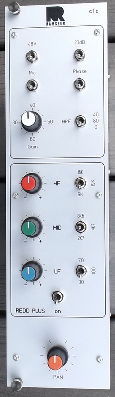
Regular readers will know I am mechanically dyslexic and I have zero artist skills as well. So I was very pleased when a fellow groupDIY member Jean http://cdlei.blogspot.com/ offered to design the front panel layouts  and rationalise the placement of controls and switches on front panels across the entire mixer! We had already been discussing a CTC logo to go on the front panels and the discussion somehow morphed over a period of about 11 months into complete front panels designs Bottom line is here is the design that Jean came up with for the Mark 3 updated 8 tracker design.


The above image is of the very first front panel to this design received from Schaeffer. At the top are three toggles that control phantom, phase and mic/pad/line selection via relays. Beneath these is the rotary mic gain switch and the HPF. Next comes the 4 band REDD EQ section with four stepped boost/cut controls each with an associated three way toggle that selects the frequency. The last section contain the tape return section with its level control and three way mode switch. And of course right in the top right hand corner is the new CTC logo that started it all off.

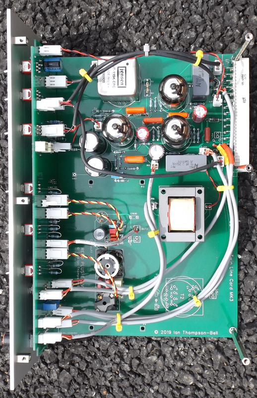
A few days ago, the received the latest main board PCB incorporating the 4 band EQ , the new low profile output transformer and the tape return input. So here is the first picture of a completed Mark III 8 tracker channel amp.


The three tubes are at the top and to their right is the 32 way connector that plugs into the backplane PCB. About half way down the board are the four orange coloured relays for low level switching with the mic input transformer to their left. The black cable connects the mic input to the relays and is the only really low level cable now. Just to the right of the mic transformer is the ribbon cable connecting front panel switches to the relays. The bottom right hand corner has the Electro Mag output transformer and to its left are the four bands of inductor based EQ. A couple of 6 way ribbon cables connect the EQ to the front panel. The only part of the circuit not yet cables is the tape return which passes via the small transformer just above the Electro Mag.

Tuesday 5 November 2019

Crossover Tube Mixer

In the automotive world, crossover vehicles are all the rage, so why can't it be so in the tube mixer world?

The Mark 3 tube mixer is very different to the original EZTubeMixer but they do share some core technology, particularly the the basic 3 triode gain block used throughout the designs and the use of standard Eurocard sized PCBs and a 32 way connector to the backplane PCB. The main differences are in implementation:

  • The Mark 3 uses a different pin out on the 32 way connector. This moves the power connections to the centre of the connector ,which makes power tracking simpler and shorter, and adds two more balanced inputs/outputs.

  • The EZTubeMixer uses standard  Eurocard specific extruded aluminium cassettes to house  modules. These are very expensive and wasteful of space. The Mark 3 dispenses with the cassette and replaces it with a single sheet of steel shielding and some stand offs.

  • The EZTubeMixer mounts controls directly on the Euocard PCB. This means that every time you want to change the position of a control you have to layout the whole Eurocard PCB again. The Mark 3 design mounts controls directly to a separate PCB that sits 10mm behind the front panel. So, if you need to change the position of a control , the main Eurocard PCB remains unchanged. All you have to do is change the smaller front panel PCB. A set of standard pots, toggles, push buttons and rotary switches has been selected all of which are capable of fitting directly to the front panel PCB which is 10mm behind the front panel itself.

  • The EZTubeMixer mounts controls directly on the Euocard PCB. This, combined with using an aluminium extruded cassette, means that a typical front panel control is a minimum of 20mm from the left hand edge of the front panel. This is not an issue if the front panel is 70mm wide but in the Mark 3 it is only 35mm wide. The Mark 3 dispenses with the extruded cassette which means front panel controls can now be mounted as little as 9mm from the edge of the front panel which is much better for a 35mm wide module.

  • The EZTubeMixer mounts tubes directly on the Eurocard PCB so they stick out horizontally. This is the principle reason why the EZTubeMixer modules are 70mm wide. The Mark 3 mounts each tube on a small PCB along with a right angled connector (white in the second picture below). This connector is then soldered to the Eurocard PCB so the tubes sit vertically. This is what allows the width of the Mark 3 modules to be shrunk to 35mm. However, the tubes now consume a considerable amount of PCB area which makes PCB layout harder. As a result, the new Mark 3 version of the Twin Line Amp (TLA) has no room for the two input transformers found on the EZTubeMixer  version.

EZTubeMixer version of Twin Line Amp


Mark 3 Twin Line Amp (TLA)

As you can see in the picture above, there is just about enough room on the new TLA board for a couple of small OEP input transformers but if they are fitted there is no room for front panel controls. You will also notice the two large electrolytic capacitors lying on their side near the bottom of the PCB. These are in series with the gain setting resistor. They are 100uF 250V electrolytics. At the time this board was built I could not find a radial lead version that was short enough (there is about 25mm of height available) so I was forced to lay them on their sides. I have since sourced a version  that is 25mm high which has freed up a little more PCB space

Theory into Practice

The most recent mixer I built was for a customer who wanted to use large rotary faders so it made sense to use 70mm wide EZTubeMixer style modules. However, as this was a custom design, which meant new Eurocard PCB and front panel layouts would be required, it made sense to decouple front panel design from the main Eurocard PCB design - which is exactly what the Mark 3 aims to do.

So this mixer became a combination of EZTubeMixer and Mark 3 - in other words a crossover mixer.

It has a new 6U Eurocard PCB which includes the active electronics for the mic pre and EQ gain make up (essentially the EZTubeMixer TLA cut and pasted). The tubes are mounted horizontally just as in the EZTubeMixer design. However, the 32 way connector has been changed to conform to the Mark 3 pin out. The PCB also holds the input transformer (Jensen) and the output transformer (Electro Mag). This PCB also holds the LC components of the EQ.

The front panel is built using the Mark 3 method with all the controls mounted on a separate PCB that is mounted onto the front panel. The EQ is a version of the REDD EQ modified to have three selectable frequencies on all three bands.

Crossover Channel Module
The picture above shows a completed channel module. The front panel and its PCB is on the left. The three tubes and the input transformer are at the top. The 32 way connector  is top right. Just below centre right is the newElectro Mag output transformer. Below the middle left are the EQ components

You can see the three stand offs on the right hand side; two on the 32 way connector and one at the bottom right hand corner of the PCB. These, together with the three small blocks you can see on the front panel, are used to mount the 1mm thick galvanised steel screen. Together these form a light weight surprisingly strong module with good screening.

70mm wide channel module
The front panel layout is conventional. The top section is the mic pre with gain switch plus toggles for mic/line, phantom, phase, 20dB pad and HPF. Beleow that is the 3 band REDDPLUS EQ with three selectable frequencies per band and lastly right at the bottom is the pan control. As you can see there is pleny of space on the 70mm wide front panel.

The completed mixer looks like this:


Conclusion

The build of this mixer, although very much in the style of the EZTubeMixer, has allowed me to prove many aspects of the Mark 3 design.

Monday 4 November 2019

Custom Output Transformers

Introduction

After testing a range of 2:1 ratio output transformers for the new 35mm wide modules of the Mark 3 mixer, it became apparent that there is no off the shelf transformer with the required performance that fits in the module. The only transformer with a satisfactory performance is the Carnhill VTB 2291 which is far too big but will now be the standard by which all others are judged.

 After some discussion on groupDIY, CJ came up with a design that appeared to meet the parameters of the specification, in particular the requirement not to saturate at 20Hz when outputting +22dBm into a 600 ohm load. As no off the shelf solution seemed to exist I looked for a local transformer manufacturer who was prepared to wind a custom transformer for me. The nearest I found is Electro Mag Ltd based just outside Kings Lynne in Norfolk. 


I passed CJ’s design to them, and after some further discussion they made a prototype based on a modified bobbin and an EI245 core. The results of testing this transformer are shown below.

Inductances

The primary inductance was measured as 32H at 100Hz

The primary leakage inductance was measured as 5.95mH at 1KHz

The secondary inductance was measured as 8H at 100Hz

The secondary leakage inductance was measured as 1,35mH at 1KHz

DC Resistances

The primary dc resistance was measured as 178 ohms

The secondary dc resistance was measured as 90 ohms

+16dBm Distortion

Distortion was initially measured at +16dBm into a 600 ohm load from 1KHz down to 10Hz. The driving source was a standard Twin Line Amp (6922 based SRPP stage with overall negative feedback). Output impedance is approximately 150 ohms. The results are shown in the table below alongside the VTB2291 results for comparison.


Frequency
Elecro Mag Distortion %
Carnhill Distortion %
1000
0.008
0.031
400
0.008
0.036
200
0.0095
0.035
100
0.014
0.033
80
0.017
0.024
63
0.022
0.023
50
0.030
0.027
40
0.043
0.035
32
0.067
0.05
25
0.12
0.084
20
0.25
0.16
16
0.66
0.37
12.5
2.21
1.3
10
6.42
4.19

22dBm Distortion

Distortion was then measured at +22dBm into a 600 ohm load from 1KHz down to 20Hz. The results are shown in the table below alongside the VTB2291 results for comparison.


Frequency
Electro Mag Distortion %
Carnhill Distortion %
1000
0.03
0.046
400
0.029
0.046
200
0.032
0.043
100
0.031
0.044
80
0.033
0.042
63
0.036
0.042
50
0.052
0.050
40
0.11
0.086
32
0.31
0.22
25
1.11
0.85
20
3.24
2.61


20Hz Distortion versus Level
Lastly, the effect of output level on 20Hz distortion of the Electro Mag transformer into a 600 ohm load was also measured. The results are shown in the table below.


Level dBm
20Hz Distortion %
+22
3.24
+21
2.18
+20
1.38
+19
0.87
+18
0.51
+17
0.33
+16
0.25
+15
0.19
+14
0.16
+13
0.13
+12
0.12
+11
0.11
+10
0.099
+4
0.088


Frequency Response
Next, the frequency response from 20Hz to 40KHz  at +4dBu into 600 ohms was measured using a Lindos MS10 test set. The results are shown in the table below.


Frequency
Relative Response dB
20
-0.5
31
0.0
40
+0.12
50
0.0
100
0.0
315
0.0
1000
0.0
6300
0.0
12500
0.0
14000
0.0
16000
-0.12
20000
-0.12
25000
-0.12
31500
-0.25
40000
-1.0


Conclusions

Initial test results indicate that this transformer basically meets the specification. Its performance exceeds that of all of the other small transformers tested particularly at low frequencies. It also compares favourably with the Carnhill VTB2291 which is several times its size. In particular:

  • The primary and secondary inductances seem to be satisfactory at 100Hz. The measured frequency response indicates they are adequate also at 20Hz

  • The primary and secondary dc resistance are very similar to those measured by CJ. The secondary dc resistances are identical. The primary dc resistance is a little higher but CJ did not split the primary winding into two.

  • At +16dBm into 600 ohms its distortion is equal to or better than the VTB2291 down to 50Hz. Below that frequency its distortion is never more than 4dB worse than the VTB2291. A very creditable performance for a transformer a quarter the size of the VTB2291.

  • At +22dBm into 600 ohms its performance is similar to that at +16dBm. At 50Hz and above it is better than the VTB2291. Below 50Hz it is never more that 4dB worse than the VTB2291. You only have to reduce the level by 1dB for it to be as good as the VTB2291.

  • Frequency response is within 0.5dB from 20Hz to 31.5KHz and just 1dB down at 40KHz

 The only downside is this transformer is still not quite small enough to fit inside a 35mm Mark 3 module. Initially it was thought that with some minor modifications to the mechanics it could be made to fit but this turned out not to be practical. Nevertheless, this transformer has been used in other tube projects with considerable success.

Electro Mag Production EI245 transformers


So the search continued. I spent some time looking at some of the first Neve 35mm modules and soon realised they had encountered the same problem back in the 1970s. The earliest Neve 35mm modules did not contain an output transformer; it was mounted externally. Only later did they use an internal one and it was quite large but rather flat.


Then by chance, work in a non-related area identified possible UI laminations and bobbins that could realise a low profile transformer only 25mm high and which would also provide a lot more winding space than the earlier EI transformer. It too was rather large and flat so it looked like I was moving in the right direction. I know very little about transformer design but as the saying goes, I know a man who does. Some UI transformer components were obtained by Electro Mag, who built the original EI transformer, and some were sent to my friend Volker who had kindly agreed to build some prototype transformers.

Electro Mag EI245 vs Volker's UI prototype


Detailed tests of the first Volker prototype and a production prototype have now been carried out and the results are as follows:

Inductances

The primary inductance at 100Hz was measured at 24 Henries. The secondary inductance at 100Hz was measured at 6 Henries. These values are about 75% of the values of the CJ design.

DC resistances

The primary DC resistance was measured as 70 ohms. The secondary DC resistance was measured as 21 ohms. These are considerably lower than the values of the CJ design principally because the much larger winding space allowed a larger diameter wire to be used

Frequency Response

The frequency response was measured at +20dBu into a 600 ohm load. The frequency response was within 0.01 dB from 1KHz to 31.5KHz. It was 0.25dB down at 20Hz. and 0.75dB down at 40KHz. This is even flatter than the response of the CJ transformer.

Distortion Tests

Distortion of Volker’s prototype was measured at various frequencies at a level of +20dBu into a 600 ohm load. A Lindos MS20 was used as the reference signal source and REW was used to analyse the resulting output spectrum. The amplifier used is a standard Twin Line Amp design operated at 340V HT for reduced distortion. The amplifier distortion is predominantly 2nd harmonic and the transformer distortion is predominantly third harmonic. Both of these along with the total harmonic distortion were measured at each frequency. The results are shown in the table below:
 
Frequency
REW level
2H %
3H %
THD %
1000
-10.4
0.025
0.039
0.046
100
-10.5
0.028
0.042
0.053
80
-10.5
0.031
0.049
0.058
63
-10.5
0.033
0.058
0.057
50
-10.5
0.034
0.070
0.078
40
-10.6
0.034
0.087
0.093
31.5
-10.6
0.035
0.11
0.12
25
-10.6
0.035
0.15
0.15
20
-10.8
0.039
0.21
0.21
16
-11.0
0.045
0.33
0.33
12.5
-11.2
0.042
0.61
0.61
10
-11.4
0.049
1.8
1.81


The second harmonic distortion remains low, increasing from 0.025% at 1000Hz to 0.049% at 10Hz. This is entirely due to the amplifier. The increase at low frequencies is almost certainly due to reduced open loop gain. The third harmonic distortion rises steadily as frequency decreases and is almost entirely due to the transformer. It is a very creditable 0.21% at 20Hz and equals that of the Carnhill VTB2291.

All other harmonics were at least 20dB lower than the second and third harmonics.

To establish maximum usable levels, further tests were undertaken at 20Hz, increasing the level in 1dB increments from 21dBu to 26dBu into a 600 ohm load. The results are shown in the table below:


Level 20dBu +
REW level
2H %
3H %
THD %
1
-9.8
0.059
0.24
0.25
2
-8.8
0.086
0.27
0.29
3
-7.9
0.13
0.34
0.37
4
-6.9
0.18
0.43
0.47
5
-5.9
0.22
0.58
0.63
6
-4.9
0.23
0.91
0.96


Even at these levels, the THD never exceeds 1% at 20Hz. In all cases the major distortion component is the third harmonic due to the transformer. This performance is better than the Carnhill VTB2291.

Production Prototype

In October 2019, a production prototype was received from Electro Mag, built to Volker’s design. The primary distortion tests were repeated for this transformer. The original test rig is no longer available so the tests were undertaken at +20dBu into 600 ohms using an HT voltage of 250V. The results are shown below:


Frequency
2H %
3H %
1000
0.0047
0.051
100
0.0088
0.060
80
0.011
0.066
63
0.013
0.075
50
0.016
0.089
40
0.020
0.11
31.5
0.024
0.13
25
0.030
0.16
20
0.038
0.21
16
0.044
0.29
12.5
0.048
0.46
10
0.058
1.40


The performance of the production prototype can be seen to be almost identical to that of Volker’s prototype despite the HT voltage being reduced to 250V. Due to changes in the test set up it was not possible to measure the distortion at +26dBu into 600 ohms but at +24dBu the third harmonic distortion was only 0.33% at 20Hz which is better than Volker’s prototype. Frequency response was also measured and found to be virtually identical to Volker’s prototype.

Conclusions

This transformer meets all the design requirements. It comfortably fits in the space available and always meets or exceeds the performance of the Carnhill VTB2291. The next step is to incorporate it into the 35mm channel amp modules of the Mark 3 tube mixer.

 
Electro Mag UI transformer alongside Volker's prototype